Wavelength
Wavelength refers to the distance over which a wave repeats itself. A wavelength is normally determined by putting into consideration the distance between two corresponding points that have the same period. Wavelength is usually represented by the letter lambda (λ) whereas the meter is the SI unit that is allocated to it (Beiser 2004, p. 13).
Frequency
Frequency refers to the number of times that an event repeats itself within a given time frame. For example, the heartbeat rate of a new born child is 120 beats in one minute. This means that the frequency of heartbeats of the child is 120 hertz. Frequency is usually represented by the Greek letter ν (nu) or the Latin letter f and. The SI unit for frequency is hertz (Hz) (Bhatnagar 2000, p. 3).
Velocity
Velocity is described as a vector quantity whose magnitude is given by the speed of motion and the direction to which an object is moving. It illustrates the rate of movement and the direction to which a particular body changes to. Velocity is calculated as follows
r = d / t
In this perspective, r represents the rate at which the object is traveling. It is usually denoted as v in the case of velocity. d represents the distance while t is the time that an object takes to complete the movement. The SI unit for velocity is meters per second (m/s) (Curry, Dowdey, & Murry 2000, p. 12).
Relationship between wavelength, frequency and velocity
The relationship between wavelength and frequency is regarded as inverse. This implies that if frequency is low, the wavelength is longer and vice versa. The velocity of a wave depends on the propagating media (Hobbie & Roth 2007, p.4). The connection between velocity, frequency and wavelength is conveyed by the resulting equation
Velocity= wavelength x frequency. The equation is derived as follows
Wavelength= velocity x time period
Velocity= wavelength/ time period
Velocity= wavelength x 1/time period
Velocity= wavelength x frequency
Acoustic impedance of tissue, reflection coefficient, and attenuation
Acoustic impedance of tissue, reflection coefficient, and attenuation illustrate why it is important for physicians to visualize the liver while looking through the intercostal spaces or looking under the ribs (Beutel & Kundel 2000, p. 17).
Acoustic impedance of tissue
Acoustic impedance refers to the amount of pressure that is produced once the particles of a certain object vibrate (Hoskins, Martin, & Thrush 2010 p. 25). In this perspective, ultrasound is usually reflected between different tissues in the body which have different acoustic impedances. If the impedance is great, one concludes that the material is dense (Roeser, Valente, & Hosford-Dunn 2000, p.18). While visualizing the adult liver therefore, physicians are required to look through the intercostal spaces or under the ribs in order to ensure that air, bones and other soft tissues do not interfere with the vibration of the sound waves. This way, they can manage to get more accurate results regarding the condition of the kidney.
Reflection Coefficient
In order for ultrasound to produce images, it is important for transmission and reflection of sound waves to be at a state of balance. When the ultra-pulse beam enters the human body, it comes across tissues which vary in terms of acoustic impedance. However, when the sound comes across a discrepancy between the tissues, an incident beam is usually replicated (Roy 2004, 14). Bones and intercostal spaces cause a mismatch in body issues thereby making it difficult for sound waves to penetrate deeper into the body tissues (Tole & Ostensen 2005, p. 43).
Attenuation
Attenuation refers to a drop in the intensity and amplitude of a sound wave when it travels through a certain medium. For example, in case a person goes in front of a big hall and talks in a low tone, only the people around him can hear him when he is talking. However, it is not possible for people standing at the back of the hall to hear what the person is saying. However, heat energy is usually produced whenever ultrasonic imaging process is carried out thereby leading to an 80 percent loss in energy (Tole & Ostensen 2005, p. 32). The energy that is produced is absorbed into the air thus making it to turn into heat.
Factors that determine axial resolution
Axial resolution denotes the capacity of a system to display two structures which are located close to each other. In this perspective therefore, the various factors that influence axial resolution of a system include; carrier frequency, bandwidth, aperture of the transducer, and the correlation window dimensions
Lateral resolution and the role of beam width
Lateral resolution refers to the resolution of objects in a plane that is perpendicular to the axis of an ultrasound beam. The aim of this object is to detect beams that are closely separated by tissues such as blood vessels which are adjacent to each other.
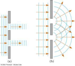
Huygens’s principle
Huygens’s principle stipulates that when a wave is used in wave analysis, every point in a wave can be regarded as the one that gives rise to the smaller waves which emanate from the bigger wave. These wavelets are usually spread in all directions and they move at a speed that is equal to the speed of the transmitting waves (Huda 2009, p. 8).
Describe TGC
Time Gain Compensation refers to the manner in which ultrasound attenuates when it propagates through the body. In the case where ultrasound is used to bring out images of biological tissues, the echo signals are normally amplified in order to allow the shallow regions of a tissue to be viewed together with the deeper regions (Hobbie & Roth 2007 p. 33). However, incorrect TGC settings affect the quality of the images that are generated through ultrasonic imaging. This is because a one gain function is not appropriate for detecting scan lines in an image. Moreover, an operator may not have enough time and experience to understand the attributes of the images that are generated. This makes physicians to adopt adaptive processing mechanism.
Dynamic range
Dynamic range is applied in instances when a person wishes to identify the attributes of a certain quantity both in high quality and in low quality. This enables physicians to identify most of the attributes associated with a particular tissue. The concept of dynamic range is applied in signals such as light and sound. High dynamic range is applied in photography in order to enable a camera to produce a picture that has elements of both bright and dark areas (Bhatnagar 2000 p.23). High dynamic range incorporates a wide range of methods to provide people with images that are of high quality thereby enabling physicians to get accurate results. On the other hand, low dynamic range is applied in computer rendering whereby multiple low-dynamic-range images are merged together to produce a high-quality image.
Reference List
Beiser, A 2004, Schaum’s Outline of Applied Physics, McGraw-Hill Professional, New York.
Beutel, J & Kundel, H 2000, Handbook of Medical Imaging, SPIE Press, Texas.
Bhatnagar, V P 2000, A Complete Course in ISC Physics, Pitambar Publishing, Boston.
Curry, T S, Dowdey, J E, & Murry, R E 2000, Christensen’s Physics of Diagnostic Radiology, Lippincott Williams & Wilkins, London.
Hobbie, R K & Roth, B J 2007, Intermediate Physics for Medicine and Biology, Springer, New York.
Hoskins, P R, Martin, K & Thrush, A 2010, Diagnostic Ultrasound: Physics and Equipment., Cambridge University Press, Cambridge.
Huda, W 2009, Review of Radiologic Physics, Lippincott Williams & Wilkins, Calofornia.
Roeser, R J, Valente, M & Hosford-Dunn, H 2000, Audiology: Diagnosis. London: Thieme.
Roy, R 2004, Science of Whole Person Healing: Proceedings of the First Interdisciplinary International Conference, iUniverse, New York.
Tole, N M & Ostensen, H 2005, Basic Physics of Ultrasonographic Imaging, World Health Organization, London.
University of Cincinnati n.d, Wave Optics. Web.