Introduction
The diagnostic accuracy of radiology departments has tremendously increased in the last three decades after the invention of computed tomography (CT).Computed Tomography is a good example of a non-invasive imaging technique thus making it applicable in imaging diagnostics. Nevertheless, there are several different types of CT artefacts which lead to marked loss of image quality(Watzke and Kalender 2004). These artefacts are majorly classified into four categories with the first one being based on physics thus entailing beam hardening, partial volume, photon starvation, as well as under-sampling artefacts. The second category involves the metallic, motion and incomplete projection artefacts which fall under the patient based artefacts. In the third class are the scanner based artefacts which commonly include the ring artefacts. Last but not least are the helical and multi-slice CT artefacts can occur including helical artefacts in the axial plane, helical artefacts in multi-slice scanning and cone the beam effect (Barrett and Keat 2004). It has been found out that low image quality will occur when the CT images are influenced by streaking, shading, rings. When theseartefacts blur its details the image contrast is reduced hence making it difficult to diagnose. The good thing however is that the new generation of CT scanners has developed apparatus, such as correction software, and operator protocol which work to reduce these artefacts(Mehran Yazdi 2009). Therefore the goals and objectives of this analysis are to identify the artefacts produced on the images during CT scans as well as to describe the possible methods that can be used to reduce or completely do away with these artefacts.
Physics-based Artefacts
Beam Hardening
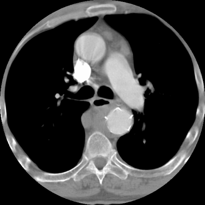
An X-ray beam is produced after the incorporation of individual with different energy levels.Thus to increase the beam hardness; the energy level has to be subsequently raised. Artefacts have noticed to be created when lower energy photons are used despite the fact that they are more quickly absorbed unlike the high energy photons as it can be depicted in Fig. 1 below. As a result two types of artefacts are created. The first being the cupping artefactwhich emerges when the attenuated beam decreases and the beam becomes harder. This is because the hardened beam is more intensive than the normal beam on reaching the detectors. Therefore the shape that results is cupped since it is produced with beam hardening. The second artefact involves streaks and dark bands which are generated when the CT scan is obtained for various cross sections with two dense objects. In most cases this type of scanning leads to the production of dark bands or streaks in the formed images. Therefore, this comes about as a result of different beam hardening that passes through objects with different tube positions such as bony regions and contrast medium (Barrett and Keat 2004).
Partial volume
In the case a scanned or dense object partially interferes with the scan plane, artefactsoccur as shown in (Fig.2). Severe shading and streaking artefactshave as well been depicted to make images unsuitable for diagnosis (Hsieh 1999). “Moreover, when two or more different types of tissues occupy the same pixel and are averaged together, partial volume effect or volume averaging artefactwill arise”(Reddinger 1998).
Photon Starvation
Highly attenuated areas or rather those with high tissue volume for instance the hips, thighs and shoulders among others, chances of serious streak artefacts occurring are usually very high. As a matter of fact if there are less photons reaching the detectors it results into more noise by the projections. These artefacts are known as photon starvation artefacts(Mehran Yazdi 2009).
Under-sampling
The quality of the image produced can be guaranteed by ensuring that a large number of projections are captured to be used in reconstructing the CT image. However, in case there is a very large space between projections, known as under-sampling, a loss of information occurs. This loss of information is want relates to sharp edges and small objects thus leading to an effect known as view aliasing (Barrett and Keat 2004).
Patient-based Artefacts
Metallic Artefacts
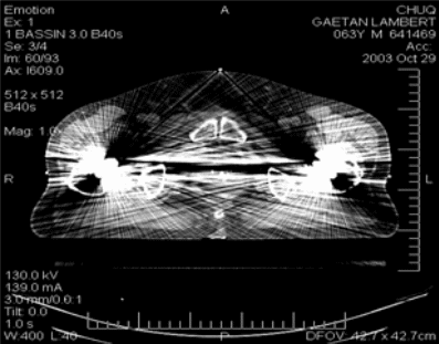
CT images are greatly affected by metallic objects since they can lead to severe streaking artefacts. The fact that they have a high density characteristic the presence of metal objects in the field of view for instance the hip prostheses, surgical clips and dental fillings eventually result into incomplete attenuated profiles (Fig.3) (Mehran Yazdi 2009). Thus the metal artefacts due to scattered radiation result into beam hardening and quantum noise which has an impact on the image quality by reducing contrast and by obscuring details (Watzke and Kalender 2004).
Motion artefacts
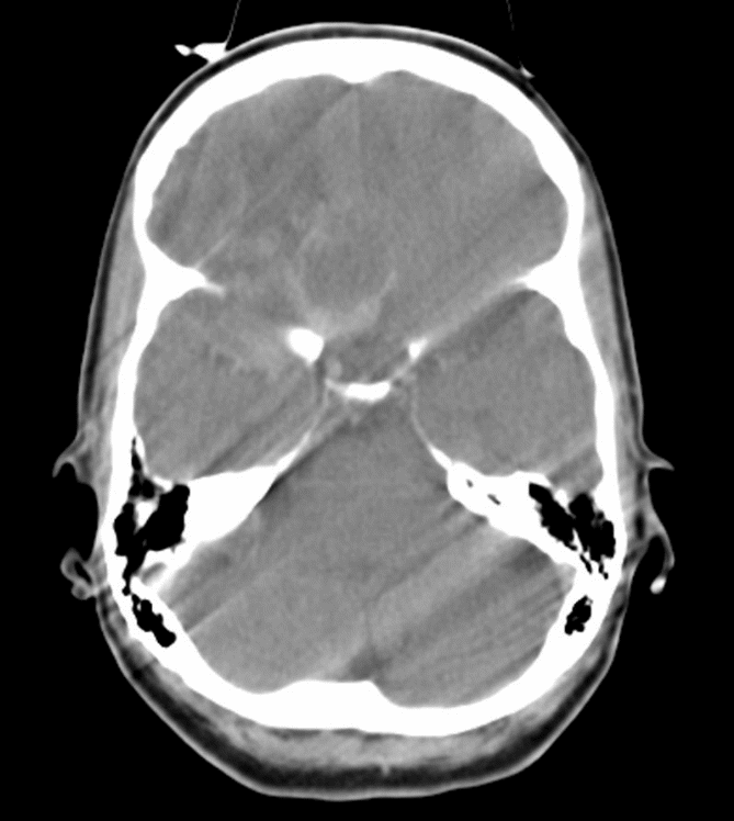
When the patient moves during the CT scan significant image artefacts occur for instance the streaks or blurring effects shown in (Fig.4). The movements are classified into two whereby there is the voluntary movement such as the movement of the chest during respiration and then the involuntary movement such as cardiac motion. As a matter of fact motion artefacts are a common problem in children or patients with severe injury or instability (Mehran Yazdi 2009).
Incomplete Projections
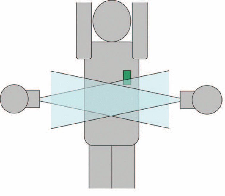
Throughout the CT acquisition, the patient is expected to lie with the examined part within the scan field of view. However, there are chances of some streaking or shading artefactsbeing produced if the patient lies outside the scan view. This happens because the computer will have insufficient information about the part to be scanned. “For example, artefacts can be caused by the arms of patient within the way of the scan instead of being raised out” (Barrett and Keat 2004).
Scanner-based Artefacts
Ring Artefacts
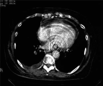
Ring artefacts come about as a result of deficient detector elements such as a gain error at a specific position in the detector array. The artefacts usually appear as concentric rings on top of the images as depicted in (Fig.5), (Jan Sijbers 2004). “This artefact occurs as a result of one or several misaligned or miscalibrated detectors in the detector array of the rotate-rotate CT system” (Jan Sijbers 2004). In most cases the ring artefacts are usually associated with third generation or rotate-rotate CT systems (Reddinger 1998). Moreover, CT scanners that are made with solid-state detectors seem to be more sensitive to ring artefacts than other scanners such as gas detectors (Barrett and Keat 2004).
Helical and Multi-slice CT Artefacts
Helical Artefacts in Single-Section Scanning
Normally, when the artefact is viewed in the helical scanner chances are that they can be seen in the sequential scanner. Nevertheless, helical interpolation and reconstruction process is what differentiates the occurrence of the artefacts. This can also be attributed to the fast change in the anatomic structures which occurs in the z direction for example at the top of the skull (Barrett and Keat 2004).
Helical Artefacts in Multi-slice Scanning
In the Multi-slice CT scanner, the helical interpolation process results into more artefacts than single scanners. The resultingartefactsappear like the windmill due to the several rows of detectors thatcross the plane of image reconstruction during the course of each rotation (Barrett and Keat 2004).
Cone Beam Effect
The dual source CT scan comprising of two detectors has the ability to obtain many sections per rotation when compared tothe single slice CT. And due to the fact that it needs a wide collimation the resulting shape of the x-ray beam will be cone-shaped rather than fan shaped. “Additionally, in the process of tube rotation data is collected by each detector which corresponds to the volume contained between two cones, instead of the ideal flat plane” (Barrett and Keat 2004). These artefacts are more distinct for the outer detector rows than for the inner ones hence similar to those caused by partial volume artefacts (Barrett and Keat 2004).
Multi-planar and Three dimensional Reformation
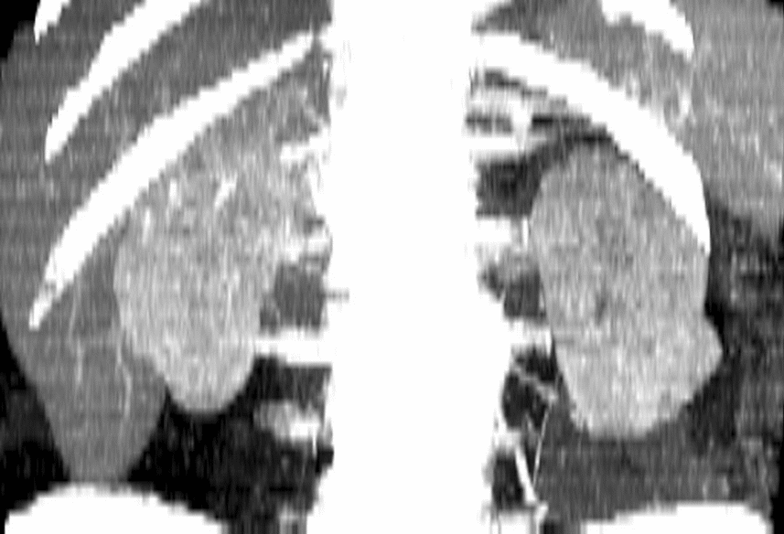
In the recent past, computed tomography has undergone significant improvementswhich have made it become a three-dimensional (3D) imaging modality from the old two-dimensional scanner. The new developments have come in hand with many applications being introduced such as multidimensional and volumetric imaging. All the same, the new techniques are associated with complex issues in the volumetric data sets that are responsible for some defects in imaging such as the variable noise distribution as well as the section thickness. In addition to this, the effects are clearly viewed in the edges or the surface of the structure. They are therefore referred to as stair steps artefacts or zebra artefact (Fig.6) on the multi-planar reformation or 3D-rendered images (Fleischmann et al. 2000).
The methods used to reduce the artefacts
Each of the artefacts has its own specific methods through which their effects can be minimized. Some of the common methods applied include;
Beam hardening artefacts
These can either be minimized by manufacturer futures or by the operator technique. In the first instance, a metallic peace by the name a pre-harden is used through the filtration technique whereby it used to filter out the energy components that are low before they go to the patient. The correction of the edge is thus done using the bowtie filter which makes sure that it passes thorough the thinner part of the patient
Another application method is that correcting using calibration in which the defects are calibrated in such a way that they compare with the beam hardening effects of the parts of the patient.”The beam hardening correction software through the application of the correction algorithms also another way to reduce artefacts whereby it is applied to images that are blurred or have dark bands for instance the bony regions” (Barrett and Keat 2004). “As a matter of fact, beam hardening is efficiently reduced by the operator technique for example, patient positioning or by tilting the gantry to avoid the bonny region” (Barrett and Keat 2004). “On the other hand, Partial volume artefacts can be minimized by using a thin acquisition section width especially when the part anatomy is changing rapidly in the z direction such as posterior fossa” (Barrett and Keat 2004).
Photon starvation artefacts
Some scanners have the ability to modulate the photon flux passing through only wide parts without changing the photon flux through the other parts such thatthe detector will receive the same amount of photons. The effect of streaking that occurs in images that are photon-starved may be minimized by use of adaptive filtration. Multidimensional adaptive filtration is another technique that is used to reduce noise levels in certain projections is (Mehran Yazdi 2009). On the other hand increasing the number of projections acquired per rotation is one way of reducing under-sampling artefacts. “More so, specialized high-resolution techniques may be applied in a bid to reduce minimize ray aliasing, for example the quarter-detector shift or flying focal spot” (Barrett and Keat 2004).
Metal artefacts
In most cases, before patients are allowed into the scanning room, they are always requested to remove any of the metallic objects they may have for instance jewellery. As for the non-removable ones special software is used to minimize their artefacts. The metal artefact reduction method (MAR) is a very efficient method that works on projection matrix. In addition, filtered back projection (FBP), maximum likelihood reconstruction and beam hardening correction are useful software to reduce artefacts caused by metallic material (Oehler, Pfaffmann, and Buzug 2005).
Motion Artefacts
The best way to deal with this is by proper positioning of the patient to prevent voluntary movement. Sedation is used in the case of paediatric with short scanning time. For children and unstable adult patients strapping on the patient couch is done to minimize the amount of motion artefacts. “Other techniques applicable include the overscan and underscan modes, software correction, and cardiac gating” (Barrett and Keat 2004). Artefacts that come about due to incomplete projections can be minimized if the patient is well positioned around the field of scan. The problem of Ring artefacts could be minimized by flat field correction technique and sonogram-processing.
Other methods that could help minimize artefacts are region of interest (ROI) selection and artefact reduction correction algorithms (Sijbers and Postnov 2004). As for the case of helical artefacts in the axial plane they can be minimized by using low pitch and thin acquisition sections rather than thick. On other hand the effect of helical artefacts in multi-section scanning can be minimized by Z-filter helical interpolators as well as by adjusting the pitch values with the detector acquisition width.
Conclusion
From the above discussion, the artefacts produced on the images during CT scans are welldescribed while giving some of the useful methods that may be used to reduce or remove these artefacts. Artefacts have been known to degrade the CT image as well as causing streak artefacts such as metallic objects, beam hardening, photon starvation and object motion. All in all, these artefactsare able to be minimized given the new manufactures technique built-in into modern scanners or partially corrected by the scanner software. Last but not least, the technician performing the scan is expected to carefully select the scan parameters as well as proper positioning of the patient so as to effectively reduce instances of artefacts.
Reference List
Barrett, J. F., and N. Keat. 2004. Artefacts in CT: Recognition and Avoidance1. Radiographics 24 (6): 1679-1691. Web.
Fleischmann, D., G. D. Rubin, D. S. Paik, S. Y. Yen, P. R. Hilfiker, C. F. Beaulieu, and S. Napel. 2000. Stair-Step Artefacts with Single versus Multiple Detector-Row Helical CT1. Radiology 216 (1): 185-196. Web.
Hsieh, J. 1999. Nonlinear partial volume artefact correction in helical CT. Nuclear Science, IEEE Transactions on 46 (3): 743-747.
Jan Sijbers, A. P. 2004. Reduction of ring artefacts in high resolution micro-CT reconstructions. Physics in Medicine and Biology 49 (14): 1-7. Web.
Mehran Yazdi, L. B. 2009. Artefacts in Spiral X-ray CT Scanners: Problems and Solutions. International Journal of Biological and Medical Sciences 4 (3): 135-139. Web.
Oehler, M., L. Pfaffmann, and T. M. Buzug. 2005. Reduction of metal artefacts in computed tomography. International Congress Series 1281: 1310-1310. Web.
Reddinger, W. 1998. CT Image Quality.
Sijbers, J., and A. Postnov. 2004. Reduction of ring artefacts in high resolution micro-CT reconstructions. Physics in Medicine and Biology 49 (14): N247-N253.
Watzke, O., and W. Kalender. 2004b. A pragmatic approach to metal artefact reduction in CT: merging of metal artefact reduced images. European Radiology 14 (5): 849-856. Web.