Abstract
A project to cater to the customer specifications for a first aid response system has been conceived. This was implemented using paging electronics in addition to the software that works in sync with it. The software was designed to gradually expand with the response of the people who are closest to the emergency. If the people who are close to the emergency point do not respond then the people in the next round are paged. This methodology is continued if they also fail to respond. A suitable methodology of development is worked out which would ensure that there is rigorous prototyping and cross-checking of the customer requirements during the design and the development phase. Based on the customer response the design is fine-tuned and the prototype is developed for the purpose. The success of the prototype and the operating complications of it would help in bettering the development process and the design will be made better.
Introduction
In a large company, some of the employees of the company are trained to be first aiders. These people are expected to help the people in need when such an eventuality comes up. In line with this requirement and the statutory need to protect its employees, the company has distributed pagers to all the people trained in providing first aid. Whenever there is a need faced by any of the staff in the company, then the company would page any one of the trained first aid personnel to attend to the problem. This was the routine that was going on in the company. The company wanted to improve the nature of first aid is provided. They wanted the first aid personnel who are among the staff to respond faster to any eventuality. This can happen only if the company could identify the person required with reference to the location and not just the name. The person closest to the incident could be swiftly directed to the incident and first aid could be provided at the shortest notice to the victim. A system is planned for this purpose in order to improve the performance of the system.
This system will be designed to make use of both electronics and the software that would work controlling the electronics.
Aim
To provide an electronic solution that would comprise both the needed electronics and the software that would control the electronics. This would ensure that the need of the customer would be met to the maximum extent possible and limitations if any will be clearly indicated.
Methodology of Execution
The electronic design will be executed in the following steps:
The requirements will be clearly noted down and a block diagram of the gadget will be designed. This block diagram will be done on the basis of a top-down design approach with the individual blocks being broken down gradually. This will be continued until individual blocks are easily realizable using known electronics or are available as a block in the market. The same is done for the software part of the design too.
This will form the overall design of the system.
Based on this information, the individual components that make up the design are done and a comprehensive breadboard is also designed for prototyping the product. A software prototype is also suggested. For this purpose, a design is worked out which will help in realizing the software with little or no difficulty. This will form the detailed design of the system.
The outcome of the prototyping is used to redesign and restructure the product. This would ensure that the product would stick to the conditions of safety, failure, and all other such requirements. The product’s final design is made with respect to these details including the manufacturing requirement and production constraints if any. The testing standards and the parameters will also be mentioned to work out a test bench design.
The final delivered document will comprise all this information, in addition to the final design as mentioned in step 4.
Customer Specifications
The First aid service in the company currently works as follows:
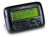
- First-aiders are trained in a company for emergency use. These people are normally a few of the working staff with other responsibilities.
- All first-aiders are given pagers for easy reachability.
- Their page numbers and their names are stored in a computer and this is usable by the telephone operator.
- When the telephone operator receives an emergency call, she pages the person after searching through the names that she has.
- The person responds to the first aid call and attends to it.
The company faces a delay in the response since sometimes the person asked to go to the first aid spot might be at the other end of the factory and might take quite some time to reach the required place. In order to avoid this, the company proposes the following changes in the existing system.
All pager numbers of the first aiders will be stored along with their name and location.
When a problem is reported, the telephone operator has to send the message to all the first aiders who are in the neighboring areas and in the same location.
The first aiders will respond to the page and confirm that they are proceeding to the spot within a fixed time frame.
If none of the paged first aiders respond to the message then the next round of first aiders in the neighboring locations to the neighboring location is identified and they are paged.
The same is repeated if they also fail to respond until someone responds to the paging messages.
The responded person would attend to the emergency.
In order to implement this, software and relevant hardware is suggested and designed in this paper.
Choice of Technology
The following technologies can be adopted to meet this requirement of the customer.
Figure 1: Comparison table on technology choice
Based on the various advantages and disadvantages given and the requirements of the customer, option number two may be chosen since it caters to the requirements and also ensures that there is no unwarranted disturbance of first aiders. Secondly, it would also ensure that the nearest person responds first and only if they are not available others are identified and sent messages to. It should also be cheaper to implement since the software is not very complex at the same time, the electronics, the pagers are already present. Though option 2 is cheaper it may not be completely satisfactory since there is no way the location of the pager can be spotted in case people are moving constantly? Therefore, the WiFi-based locator is used from option 1, and the rest of the work is done as per option 2 to implement the system.
Design Specifications
These design specifications will have a detailed block diagram followed by a set of block diagrams, expanding every one of the blocks in the first diagram. This chain is repeated until the blocks are well broken down and are easier to solve. These blocks are then individually defined in words in the detailed design for prototyping.
Block Diagrams
Overall Description of the working
The design is conceived into two major parts; One, the software, and the other, the hardware. The hardware part would be the paging unit which would take the input from the computer and send out the wireless paging message to all the pager units depending upon the choice. On the software front, the telephone operator would enter the details of the emergency location, and based on that information, it would spot the neighboring first aid personnel available. This is done using the method explained below. From this information, a standard paging message asking the person to get in touch with the operator is sent. The text will be: “First Aid emergency! Please contact the telephone operator!” This message will be sent to all the people in the neighborhood.
If there is no response for two minutes, which is noted by the computer if there is no update from the telephone operator for the emergency recorded, then the computer by itself spots the next round of neighbors and then sends them the same message. This is continued until the entire factory is covered or someone responds to the message. If nobody responds to the situation and the entire factory is covered then the computer sends in a message to an executive of the status. If someone responds, and if the operator updates the computer of that response, then it also sends in a message to the executive in charge of emergency first aid services in the factory.
A specific routine is adopted to identify the people in the neighborhood. The algorithm for the identification is explained in the next section.
The basic assumptions made in this description are:
- The entire factory is divided into locations. These locations are mapped and they are coded.
- Every location will be identified with neighboring locations in all four directions.
Every person might be moving about in the company. His location is identified by the WiFi-enabled pager which positions the entire set of first aiders every five minutes and updates the data into the database. This updated information is used by the rest of the software. This updater will run automatically and will be using the WiFi-based paging system along with an access point to judge the movement of the first aiders in the company.
It is also assumed that every person is within the reachable distance from a calling point to contact the operator once they receive the paging.
It is also assumed that every one of the first aiders will be carrying a pager when they are in the company.
Methodology to select the neighbor
In order to select the neighboring first aid volunteers, the following methodology is adopted.
The pagers when they pass from one floor to another or one to another, they move within the WiFi Cells. The cells identify the pager when it comes into its area and transmit a code to the wifi antennas.
Every cell is numbered and has location identification. When the pager moves in and transmits its id, the cell notes it and sends it back to the computer for the current location of the cell. Every location is thus catered to by a WiFi transmitter-receiver to take care of the moving in pagers.
All locations are coded.
The movement of the pager is transferred from one cell or one wifi trans-receiver to another when the strength of the one increases over the currently existing cell.
For every location, there will be neighboring locations marked in every one of the directions. That is, for instance, Engine Room-1 will have E-Engine Room-2, W-Body Assembly Line-1, N-Paint Shop-3, and S-Paint Shop-2.
Since every location is coded, the complete description of the location will not be stored. Instead, the location codes will be stored in four columns one each for every direction. There can also be two locations adjacent to one in a direction. In which case, both are entered separated by a comma.
This methodology will help in identifying the neighboring location for any location. Based on this information, those people who are in that location are identified and paged.
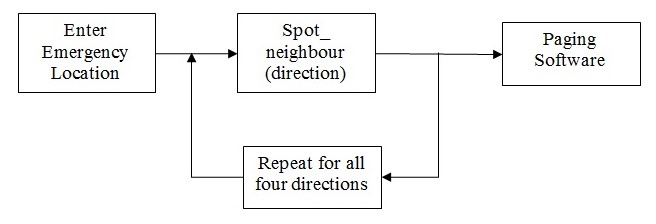
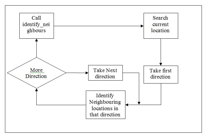
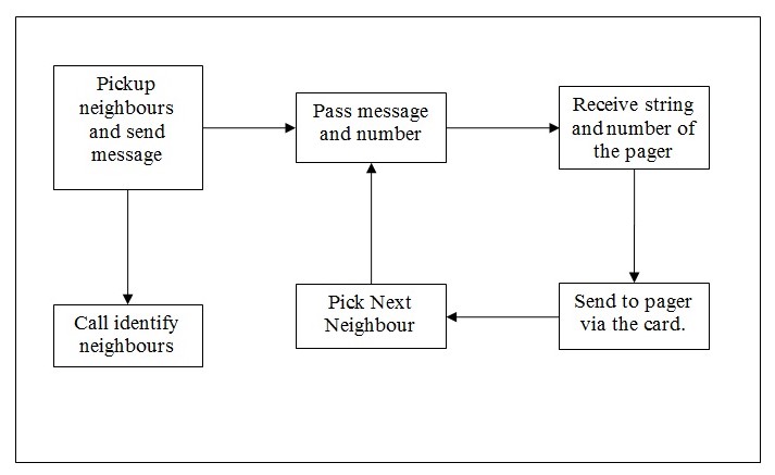
The process diagram for the usage is shown in figure 4.
The identify_neighbours would execute a search in the database that has both the location and all its neighbors listed along with the directions. The direction of the search required for that particular search is also passed to identify neighbor routine. The overall working would require the neighbors can be identified only if the direction is also passed.
The neighbor to the current location is identified in the directions required one after the other. However, the search can happen depending upon the location in multiple directions.
The pager location is identified using the cellular technology normally adopted for cell phone movement. The pager is looked at as present in the cell structure of the WiFi signals and moves from one ‘tower’ to the other whichever has the strongest signals coming out of it with respect to the pager.
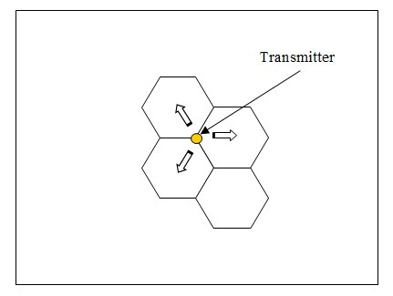
The cell structures are constructed in the office with every person moving with the pager getting connected to the strongest transmitter. The transmitter that has the largest signal strength is the one that will be identified with the specific location. Every transmitter will have its own range of cells that is under its control.
Paging Hardware
Selection of Paging hardware
The selection is decided by the size of the company in terms of an area that has to be covered by the transmission and the nature of the paging that has to be done. The paging done is an alarm type of paging. When something goes wrong, the pager will let out a beep sound and the person responding will give a call back to the telephone operator to find out what went wrong. This is not a device that might carry numeric or text data indicating who is calling or where to go. This would only help in providing the information that the telephone operator is looking for the person.
Process of selection
The transmitted signal goes in for continuous attenuation inside a building. The power of the transmission should take into account this attenuation and compensate accordingly. In line with 20 log d Path Loss law, the attenuation of the signal when transmitted in an area with no hindrance would result in a signal power loss that is governed by the formula,
- Power at destination = Power at origin – 20 log (d / d0)
The power of the transmitted signal goes down by the square of the distance. The graph below indicates the variation with reference to the distance.
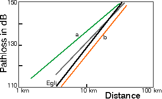
This indicates the large-scale attenuation that happens if the distance increases beyond 5 km. However, in our current consideration within a factory or work spot, the distance could go beyond 1 km and would be less than 10 km. Therefore, losses would be present though not of a very high degree. However, the losses induced in the signal due to wall penetration and other effects including moving people have been found to be present though not phenomenal. While the power of the unit needs to be in line with the decay that it is bound to suffer, it is also important that the signal it transmits is in line with the standards adopted by the receiving devices already in use.
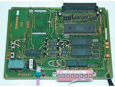
The hardware selected for this purpose need to have the following features:
- It should be a PC pluggable board.
- It should be compliant with the standards normally adopted for paging. The board should use the same standards as adopted by the paging company that has been selected for the paging services.
The operation of the paging board should be easy and should be software controllable. The operations should not involve complex commands and ideally be operable with one or two easily laid commands.
The string that it supports for paging should be in line with the pager company’s limitation which has already been selected. However, this has to accommodate the message size and should be equal to or more than 256 characters normally.
All these features should be present in the paging hardware board selected. This board will help in sending the paging messages to the pager once connected. In addition to these the following assumptions are also made:
- The board will be reasonably fault-free and if needed the spares and standby for the board will be easily available in the market.
- The board will take the power needed to drive it from the PC itself and does not require any additional power for the purpose.
- The Wifi antennas are kept at an average distance of 1 to 1.5kms from one another and the locations are also marked accordingly. The location to which the pager is closest is marked as the location of the antenna.
Paging Software
The paging software will have to be written by the project development team based on the hardware and on the requirements of the project. In line with these requirements already stated the following will be the broad requirements of the paging software:
- This will be made of reusable routines.
- This should be able to accept a transmitted string and the destination pager number as input from any calling routine.
The software should make use of the paging hardware to transmit to the destination pager number the message sent to it by the calling routine.
If there are any error conditions then an equivalent error message is given to the calling routine and if the message has been successfully transmitted a success message is given to the calling routine.
The limitation of the paging software will be that, it may not be able to work on other paging standards.
The main software would identify the neighbors using the identify neighbors routine. Using the identified neighbors, the pager numbers are identified for every one of the available first aiders in the neighboring location. For every number, the message is sent to their pager using this routine.
This software will be tied to the specific manufacturer and/or to the specific technology alone. The assumptions made here are:
- All the pagers used in the premises are made for the same technology and operational instructions. Only then, they will be able to receive messages from the paging hardware and in turn the software.
- The other assumption is that the size of the message that can be held by the pagers underuse is 256 characters and above. If they can only hold smaller lengths in characters, then the program needs to be accordingly altered.
Response from the First Aider
Once the message is transmitted to the various first aiders in the group, then any of the first aiders might respond to the messages. They respond by pressing the accept button on the pager. Once the message is accepted, the pager board gets a read and accept confirmation from the pager. This is updated into the database with the number of the pager that has sent the confirmation. More than one response is also taken and recorded. The data recorded includes who has responded and from which location and therefore, how much time he or she will take to reach the emergency point will also be entered into the system. This would be the planned response to the emergency call. This entry would also reset the emergency call registration and as far as the computer registration is concerned, the call is closed.
However further registration of the details of the call can be done in the future to capture all relevant information for the call. This will also improve the performance of the first aiders on an overall basis. Assumptions made in the program are:
- All the respondents to the messages are of equal capability and at approximately equal distances and these points are not taken into consideration when deciding on who has to be taken as respondent.
Of the respondents, whoever has called in first is taken as the person who has respondent and the data is fed into the computer. Further processing in the software is closed after this.
In all cases, the database is updated with the relevant information collected during the course of the work execution. The complete database design is provided in the following section.
WiFi Location Hardware
Block Diagram of hardware
This comprises hardware for the access point and the WiFi-enabled pagers. These pagers are also communicated over the WiFi network so that any other network charges that are incurred are also avoided. The software helps in finding the location of the pager. The signals from the access points will be available at the pager. When the pager moves from one location to the other, the strongest access point at that location will decide on the location of the pager. This will ensure that the pager’s location is clearly spotted.

Three Access Points are positioned in the building. This would help in positioning any of the pagers accurately by identifying the signal from every one of them. The strength of a pager’s signal at all three locations would help in drawing spheres for every pager around the access point. Between them, the intersection point is taken and that would form the position of the pager. This information is gathered and updated into the database from the access point. Software is written to calculate the signal strength and the strongest access point at that pager location will be the one that would the location of the pager.
WiFi location Software
Wireless strength diminishes with the increasing distance from the source. This principle is made use of in identifying the radius from the accept point at which every pager is located. All the three spheres at the radii measured from each one of them are taken for calculating the final location of the pager. The algorithm adopted for this purpose is as follows.
Let there be n positions in the office area that is already marked out. Let these be represented by a set called P which will be an array of {p1, p2,…,pn). Let there be m access points. So at any given point pi there will be m different signals occurring. Let these m access points be {a1, a2,…,am} represented by an array A. For any location represented by pi , the signal strength s from a1 is represented by a probability distribution curve.

At any position pi lets there be a set of signal strengths acting. Let this be S comprising of the set of signal strengths {s1, s2, …, sm) where s1 is the strength at pi because of access point a1, and so on. The problem is to identify the location at which this is happening or the probability P(pi|S) for the position can be obtained when it is maximized. The probability can be represented as:
P(pi|S)=( P(S|pi) P(pi))/P(S)
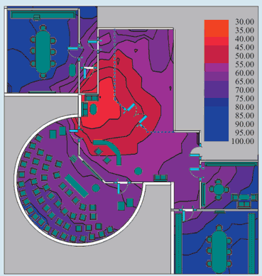
Based on this equation, it could be seen that the probability distribution will be dominating the way the entire work is executed. Therefore, the model will work in two phases, one the training phase and the other is the working phase. During the training phase, for a set of fixed positions in the area, the various signal strengths are taken and the locations are mapped. The entire area will have a map of signal strengths from various access points. This will clearly indicate the extent up to which the exact location can be accurately pinpointed. This training will help the system to assess itself and locate the positions based on this information. Subsequent to this training, the system would be ready to identify the locations that are being sought after.
The number of access points in the system can be increased and the accuracy of the spotting would also go up. However, there should be a minimum of three access points reaching any given location in the system. The location of the pager is, therefore, the strongest access point at the current pager location.
Detailed Design for Prototyping
Bill of Materials
The following hardware components are required:
- Personal Computer P4 and above, 2GB RAM, 40GB Hard Disk Drive, A CD / DVD Drive, a monitor, keyboard, and mouse of the user’s choice.
- A Wireless card for wireless paging services. Most of the paging cards subscribe to one of the standard paging protocols viz., FLEX, REFLEX, POCSAG, ERMES. This need not be two-way. It is enough if this is a one-way paging system capable of transmitting paging messages. However, by default, the card is a two-way paging system and can be used for either. In addition, this should also carry adequate location monitoring systems for identifying the location of the paging device.
- Required cables to connect the components.
- Power supply source of the rated capacity. In order to ensure fault-free operation and failsafe arrangement, the power source need to be an uninterrupted power supply.
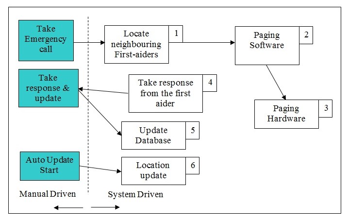
Operation Diagram
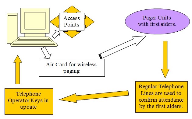
The operation diagram indicates the jobs that are driven by the system designed. In this system, the paths and blocks indicated by the amber are driven by manual means while that of the rest are driven automatically by the system. The pager message is seen by the person though driven by the system and then responded manually. The data finally that is updated as well as when the entire process is commenced is recorded by the telephone operator manually. In either of the cases, the data is then stored in the computer and further processing is done based on the same.
A standard personal computer is used based on Intel Pentium 4 or above processor. This is expected to have a basic working memory of 2GB and a hard disk of 40 GB capacity. There should be a DVD or a CD drive to make the needed installations of the software. A comfortable monitor, keyboard, and mouse for the operator to work on are needed. The wireless paging card is plugged into the computer directly for the paging requirements. The power supply and the operating instructions are picked up by the system from the computer and can be soft controlled by the computer and its software.
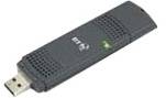
The selected card is from the Sierra Wireless Air and modem card which is comfortable for most of the common wireless applications. Typically, the modem can be controlled like a telephone line once the subscription to the wireless modem is fixed. This would ensure that the modem can call up the wireless pager or the mobile phone to message the unit. Since this is a wireless air card, the user can subscribe to any of the service providers and connect up to their network. Using the same network the air card can also send out pager messages to the other paging units.
The Air Card 880 offers a full-fledged wireless tri-band UMTS and a Quad-band GSM / Edge phone capability. This can be programmed to provide the required messages to the pagers by connecting them up to a subscriber network. The Air card is easy-to-install hardware that comes with the needed controlling software for transmitting information over a wireless modem network. However, the capability of the modem and the wireless device to act as the paging unit server is not a standard operation. This can be realized only through software that has to be made for this project. But the capability of the Air Card 880 is substantial enough to take care of the requirements of the paging server. This follows the standard PCMCIA Type II standard.
Software Design
Database design
The following tables and their structures are planned to be in the system:
First Aiders Table
Primary Key: First Aider Identification Number
The location code is updated by the entry system to every floor when any of the first aiders pass out through the door or they enter a floor.
Emergency Call registration table
Primary Key: Emergency Call Id
Location Code table
Primary Key: Location Code
Neighbourhood table
The direction follows the standard code namely, E, W, N, and S, to indicate the directions.
Primary Key: Location Code + direction.
Use Case Diagrams
From the use case diagram given below, the following major use cases could be identified.
- Receive Call
- Record Call
- Page neighbors
- Identify neighbors
- Page Message
- Respond to Call
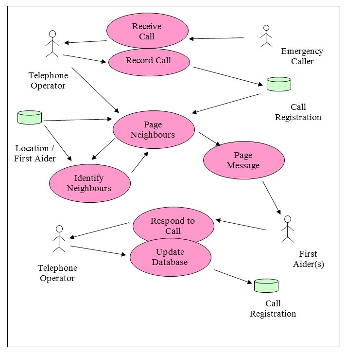
Every one of the use cases that is being specified in the diagram is described in the following section. The data is saved in the database tables as indicated in the previous section.
Assumptions: The database has data pertaining to the location and the codes for the location. It also has data pertaining to the first aiders and the place they are normally available. This information is entered using an entry screen into the database or directly fed into the database. This information is not shown in the use case diagram above. The use case diagram otherwise, covers all the aspects of the project.
Use Cases
Receive Call & Record Call
- Actors: Emergency caller and the telephone operator
- Information Shared: Nature of emergency, data and time of emergency, location of occurrence.
- Description: The emergency caller makes a call to the telephone operator and informs of the emergency, the nature of the emergency, and the place it has occurred. This information is recorded by the telephone operator in the database.
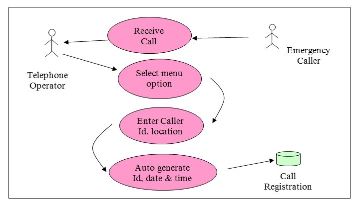
Use Case Steps:
- The telephone operator receives the call.
- Clicks on the menu option ‘Receive Call’ and opens the screen to record the call details.
- Even when the emergency caller is online, the telephone operator records the location, the emergency caller’s name, and a short description of the nature of the emergency.
- The emergency identification number is automatically generated.
- The date and time in the system are taken up and stored in the database table for Emergency Call registration.
- The use cases for the record and the receive call are overlapping and the work is executed as indicated above.
Page neighbors
- Actors: The telephone operator closes the process. However, this is an automatic process that is started off by the computer once an emergency call is registered. This uses data from the database tables.
- Information Shared: Data pertaining to location, direction, neighboring locations, and emergency call id are used along with the pager numbers.
- Description: The system starts the process of identifying the right first aiders who need to be paged once the registration is completed. Based on the location of the emergency, the neighbors in all directions are identified. In the next round, only the direction opposite to the direction of the emergency location is used to identify the neighboring locations. Those people who are first aiders and who are in the location specified are sent the paging messages.
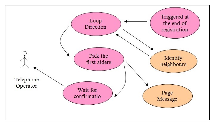
Use Case Steps:
- The program is triggered when the data is entered into the call registration and if the First aider Id in the emergency registration table for that record is blank.
- The direction is maintained in the order East, West, North, and South.
- The program triggers identify neighbor locations by sending the current location and the valid directions for that location. In the case of the emergency location itself, all four directions are valid.
- The neighbor identifying program returns the neighboring location and the direction it is from the emergency location. This is saved in a two-dimensional array of location and direction including the level. The level is the first neighbor when the process starts. When the next rounds of neighbors are identified, then the level becomes two, and so on.
- From the neighboring location identified, the first aiders in that location are searched and picked up.
- The pager numbers of these first aiders are also picked up from the record.
- A message is sent to them asking them to call the telephone operator for an emergency at a neighboring location.
- Confirmation of a response from the telephone operator is waited upon. If there is no confirmation, then the next level of processing starts in the same loop.
The use case ends when the telephone operator responds to the confirmation message or when there are no further neighborhood locations found. This happens when the process for identifying neighbors returns an error.
Every routine started is a separate thread and therefore, can have multiple threads running at the same time.
Identify neighbors
- Actors: This process is triggered by another process. In this case, it is the page neighbors process.
- Information Shared: Current location code, the directions list where the neighbors need to be identified. This process returns all the neighboring location codes and their directions.
- Description: The identified neighbors use the current location code and the list of directions provided to identify neighbors in every listed direction of the current location. It returns the neighboring location code with the direction code.
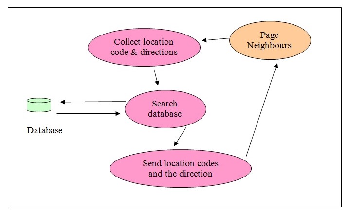
Use Case Steps:
- This use case is automatically triggered by the page neighbors process.
- It picks up the neighboring location code for every direction listed for the current location.
- This information is passed back to the calling routine in an array. It has the location code and the direction of the neighboring location with reference to the current location passed in.
- Once the list of directions sent in ends, the process stops.
- This would also ensure that the process returns both the neighbor’s location and the direction.
Page Message
- Actors: First Aiders
- Information Shared: First Aiders’ pager numbers and the message that has to be sent to them.
- Description: This process is called or triggered by the Page Neighbour use case. The calling use case passes the pager number of the first aiders who need to be informed. This process pages the message to the said number.

Use Case Steps:
- This use case is triggered by the Page Neighbour routine.
- The data with the pager number and the message is received from the calling routine.
- This is then communicated to the pager using the standard paging protocol of the paging card available on the computer.
- If there is any error faced during the process, an error message is returned to the calling use case. This error message will be having the error number received from the hardware.
Respond to Call and Update data
- Actors: Telephone Operator. The First Aider acts externally to the software process.
- Information Shared: Date and time of response and the responding first aider’s name.
- Description: The first aider who is close to the emergency and receives the paging message, responds to the message. His or her call is received by the telephone operator and the response is entered into this process. This will stop the ongoing thread of page neighbor and this process is stopped by the telephone operator once the data is entered. Both the processes, respond to call and update data are overlapping and starts off even when they respond to call is in process.
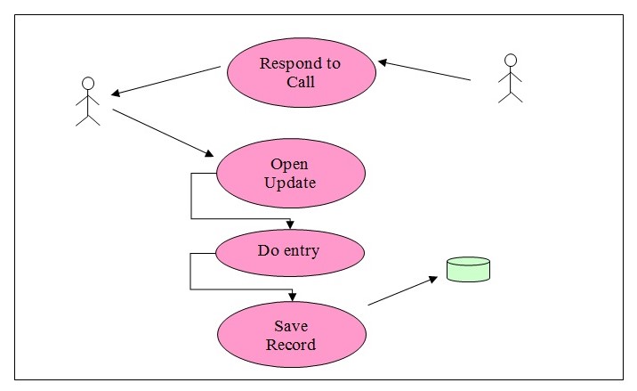
Use Case Steps:
- The telephone operator receives a call from any one of the paged first aiders.
- The telephone operator opens the screen for entering and updating the data pertaining to the first aider.
- The emergency call-id is opened
- The data and time are automatically captured by the system and displayed in the relevant fields.
- The name of the first aider is entered by the telephone operator.
- The telephone operator then saves the record and closes it.
- The process would then stop the thread from paging the neighbors.
Performance and Manufacturing Considerations
The following performance and manufacturing considerations will be taken:
The system should be able to respond within the stipulated time in spotting the neighbors and then transmitting paging messages to them. This being a critical application time is very important; it is also important for the entire software to be up and running as long as the people in the factory are working. The criticality of the software is to be considered and ensured.
While manufacturing the software and the hardware, these points on the criticality need to be kept in mind. The operating voltages of the system will withstand variations as stipulated in the power supply of the computer. The power supply is made as stable as possible.
The system is rated to work in low voltages which are not harmful to man and therefore, no special safety precautions might be needed while manufacturing it or during transport of the same.
The product manufactured should ensure that it is made easily maintainable and that it would work towards bettering the serviceability of the product and also to reduce the failure rate of the equipment made. Standard fixing screws should be used to fix the paging board so that it is easily maintainable by any of the service engineers.
The product will be continuously rated and would work round the clock, 24 hours a day and 365 days a year.
The software needs to be tested for bugs and should be exhaustively tested using a rigorous testing acumen that would ensure no bugs are carried forward when the product is delivered. This is required since the software is prone to bugs and it is better if the software is repeatedly tested for various combinations of operations to identify any specific problem that might arise in the system.
For the manufacturing process, since the standard Personal Computer is used, the same is bought from the outsourced market. The card is also sourced from outside for Paging purposes.
The software is preinstalled onto the hardware and then is sent to the client’s place. After completing the installation on the computer, the same may be tested for fault-free operation as specified in the testing procedure later.
Legal, Safety and Failure considerations
It is very essential that the product adheres to certain specific safety and legal considerations which would also ensure that the project has taken into consideration the failure the project. The following safety aspects need to be monitored.
In order to ensure that there is a minimum delay in the first aider attending to the emergency reported, the closest numbers of first aiders are called. This would ensure the safety of the person who is afflicted by the emergency.
The used voltage levels in all the products are well within the normal working voltage and would not hurt the workers or the employees who are on the job there.
The intensity of the Radio Frequency waves used has been designed to be within the IEC specifications. The equipment selected for usage here confirms the IEC specifications. Therefore, they are not expected to hurt the individuals or affect their health in any manner.
There are no major legal issues faced except in the use of the frequency range which has to be licensed. The licensed range is normally called the 2.4 GHz frequency band. This varies from 2.4000 to 2.4835 GHz. This is a license-free range and therefore, does not require any special authorization to work in this range. However, if the operating frequency is selected to be anything other than the free license range then appropriate permissions and licenses need to be taken for the operation.
Apart from this, there are no other legal issues faced in this project.
The failure considerations need to be done and their alternates are listed:
The hardware failure can occur in the personal computer and also on the paging board. Since this has to be failsafe, it is better to have a standby paging board. However, in the case of the computer, there should be a hot standby if a failsafe alternate is to be planned. In this case, it was not originally considered. In order to counter this failure situation, it is important that the software and data are regularly backed up every day. It may also be backed up in a network drive every one hour to make the standby option more effective. In the case of a failure of the computer, a standby computer can be lined up along with the paging board. The data and software from the backup are to be restored on that machine before lining up. There will be an interruption of the services to that extent. During this period, it has to be manually managed by the telephone operator. A standby person may be planned to assist the telephone operator under such conditions.
Failure can occur in the software itself. Software bugs though not are very common are reasonably common. A failure in the software could hamper the work being carried out automatically. Under such conditions, the manual execution of the job is to be carried out after duly recording the events that led to the failure. This would help in sorting out the problems faced during the failure. However, it is essential that a standby plan is put in action under such circumstances. A person may be nominated to assist the telephone operator under such conditions to carry out the job manually.
Failure can also happen when a power failure happens and there is no way to keep the systems up and running. In order to safeguard this specific issue, a battery-driven uninterrupted power source has been planned and incorporated to drive the computer and the affiliated hardware.
Failure can also happen if none of the first aiders respond to the call and the software has reached the outermost neighborhood. In which case, no one in the company has responded to the call and therefore, it is very essential that there is a hot standby first aider who is called in case of such failures and who is always available. This person can also be used under any of the other failure conditions listed above and if no one has responded or could be reached for the failure within a reasonable time frame.
This standby person who is also qualified as a first aider is a strong fallback arrangement for all kinds of foreseen as well as unforeseen failures. However, it should not be a practice to make use of the person all through for every kind of failure. He or she should be used only as a standby.
Testing and Performance specifications
Testing has to be carried out to ensure that the performance specifications of the equipment are fully met. The performance specifications have been decided based on the original requirements of the system identified at the beginning of the project. Performance specifications are given below:
- Auto identification of the neighborhood pager numbers of the first aiders.
- The first aiders should be dynamically moving and the software should be able to identify them based on their current position.
- Call registration and tracking should be done.
- Call confirmation from the first aiders should also be recorded to identify the time taken to respond to a call for an emergency.
- Auto paging by the computer using the paging card.
All these performance specifications should be met by the system designed. In order to check whether these are met, the following test cases should be performed.
Test cases
One more column in the name of remarks is added to the table and the results are recorded in the remarks column. Whether the test was successful or not is indicated by the status column. This will indicate whether the test was a success or not a success and whether the product needs to go through specific repairs. Once the product meets all these test requirements, then it meets the specifications originally planned. Only then the product is acceptable.
Final Design Papers for Manufacturing
The design papers for manufacturing will include the overall software specifications including the use case diagrams, use case specifications, and the test cases listed earlier. In addition to this, the overall General Arrangement drawing would help in positioning the cards and the computer on the hardware side.
All these would make up the final design for the production of the relevant software and the equipment.
Cost
Conclusion
A complete design has been carried out for the requirements identified at the beginning of the project. These were collected from the users and the client specifications have been put in. The design has been done to take care of all these requirements and comprehensive software and hardware design has been laid out. At every stage, the explanation has been provided along with needed drawings to enhance the readability and ease with which the features could be understood. In addition to these, the test specifications and test cases have also been mentioned. All these can be made use of for the production of the required equipment. The design also provides for the tracking and updating of the people and their movements in addition to alarming or paging them when there is an emergency first aid attention required.
Photos
Annexure
Pseudo Code
The pseudo code is given for every use case rather than the actual program since it would mean that the entire project has to be executed and assembled before trying out the actual code. However, the pseudo code is a fair representation of the software structure and the happenings in the software including the flow and the algorithm.
Menu option
The following menu options will be supported by the system.
- Record call
- Logoff
When the program starts the log on name and password is taken to ensure that the user is an authorised person.
- Collect username and password
- Authenticate user name and password
- Display menu for the above options.
- Let this be the opening screen.
Record Call
- Record call option should initiate the record call routine.
- Collect the particulars of the call. This would include calling person name, location, nature of emergency.
- Date and time of the call should be taken from the system.
- This is recorded in the computer database maintaining these details.
Page neighbours
- Identify neighbours by calling the identify_neighbours routine.
- Using the identified neighbours, page the neighbours with the message that an emergency has happened, please contact the operator.
- Once the communication is sent, lapse into a wait start until either a respond occurs or a time limit for lapse (10 minutes) occurs.
- In the first case, the job is stopped. In the second case, once the first lapse is over, please move on to the next round of neighbours. Identify by calling the next round of people and wait for response.
Identify neighbours
- Neighbours are identified using the algorithm defined in the earlier sections. This is done by using a structured approach making use of the direction and the current location to identify the victim’s neighbours.
- Any person close to the neighbour is possible to respond to the emergency.
Page Message
Message is paged using the paging hardware.
- Use standard communication software for sending out paging messages to every one of the identified.
- Fix message to be sent
- Call object to send messages through the pager boards
Respond to Call and Update database
When the call is responded, the following action is done:
- The call is responded by any of the users who has a pager and who thinks he is nearer to the service.
- The user informs that he can render service to the victim by pressing the acknowledge button
- This message is transferred back to the software.
- The software keeps polling for the input after sending out the paging message.
- When an acknowledge comes in, identify the pager from which it comes in and the date and time of the system at that point in time.
- This is saved in the database and is reviewed for later use.
Annexure I
Software Code for the system
//Location of the pager
#include
#include
location(int pno)
{float signal_strength[10]=0;
int i, max, signalcount=0;
int loc_id=0;
PORT con[10];
signalcount=check_signal(pno);
if (signalcount>10)
{printf(“Error! Number of signals cannot be more than 10”);
return();}
for(i=0; i<signalcount; i++) { con[i]=connect_port(wireless_port, pno, i); signal_strength[i]=strength(con[i]); if (signal_strength[i]>signal_strength[max])
max=i;}
loc_id=id(con[i]);
return(loc_id);}
//identifying the neighbors
neighboring_locations(int *nl[], int loc_id)
{File *cn;
int i;
struct loc_rec *fps;
cn=connect_db(loc_table);
fps=select_rec(loc_id);
for(i=0;i<6;i++)
nl[i]=fps.neighbor[i];}
//main routine
main()
{int loc, i, *neigh[6];
char *aiders[10], msg;
loc=record_problem();
neighboring_locations(neigh, loc);
for(i=0; i<6; i++) {identify_aiders(aiders, neigh[i]);
page_aiders(aiders, msg);}}
//record the problem reported
record_problem()
{struct problem_rec pr;
curpos(10,10);
printf(“nEnter Person reporting:”);
scanf(“%s”, pr.person);
curpos(12,10);
printf(“nEnter Location:”);
scanf(“%4d”, pr.location);
curpos(14,10);
printf(“nEnter Problem Details:”);
scanf(“%s”, pr.problem);
cn=connect_db(problem_table);
save_dbpr(&pr);
return(pr.location);}
//identify first aiders who are in the neighborhood.
//n is the neighboring number
identify_aiders(char *fa[], int n)
{int i, j=0;
struct aider *ar;
File *fp;
fp=connect_db(aider_loc);
setcursor_naid(fp, n);
do
{ar=get_rec(fp);
fa[i]=ar.aider;
i++;
} while (!eof(fp) && i<10);}
//Aiders to be paged after receiving their identity numbers
page_aiders(char *adno[], char *message)
{int i=0;
for (i=0; i<10; i++) send_msg(adno[i],message); //adno is the pager number of the aider } —————– Program 2 This program keeps running on the system. Whereas the first one is run only when needed. //identify the loocation of the aiders and update their records. main() { int pager; struct aider *ar; File *fp; fp=connect_db(aider_loc); setcursor_naid(fp,0) while (!eof(fp)) { ar=get_rec(fp); ar->loc_id=location(ar->aider);
fseek(fp, 2, (-1) * sizeof(*ar));
save_dbaidloc(ar);}
References
Don Johnson (2005) Wireless Channels. Web.